Klystron/Focus Coil Removal
and Replacement
Extracted from EHB6-511
7.6.22 Klystron Tube V1/Focus
Coil L1. The following procedures describe how to remove the klystron
tube and focus coil and install replacement units. It is not necessary
to remove the focus coil to remove the klystron. However, the klystron
tube must be removed before replacing the focus coil.
7.6.22.1 Equipment Required.-
The following special equipment is required to
remove and install the klystron
tube:
Name
Quantity
Torque wrench, 3/8 in. drive,
1
30-200 in. lbs
Drive extension bar,
1
3/8 in. x 6 in.
Drive adapter, 3/8 in.
1
to 1/4 in.
Hex head driver, 1/4 in.
1
drive, 3/16 in.
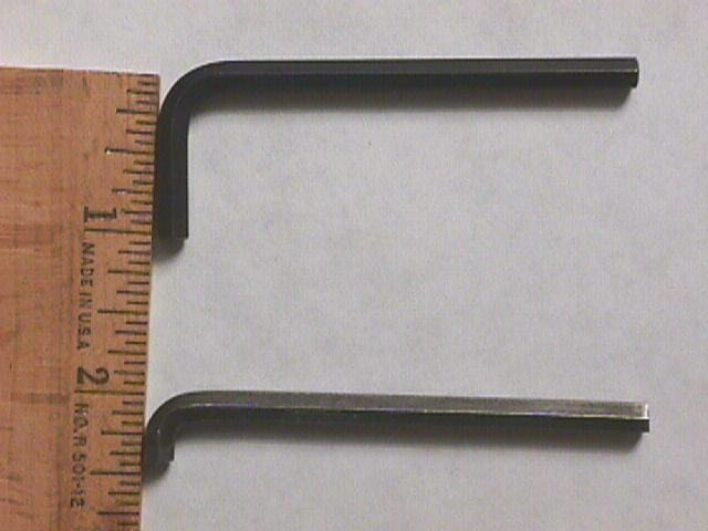
Allen wrench, 3/16 in.,
1
modifed
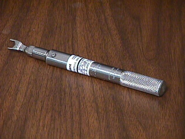
Torque
wrench, 5/16 in.
1
open end, 5-15 in. lbs
4x4x15-inch wood block
2
(for temporary focus
coil pallet)
Chain fall, 1/2 ton, special
1
lift (10 ft)
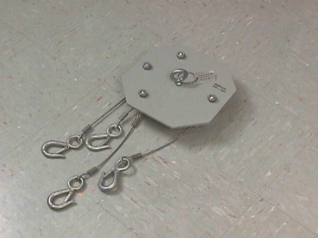
Plate
sling
1
Klystron tube container (empty)
1
Locking/sealing compound
As required
Lubricant, silicon grease
As required
Oil
tank dolly
1
Waveguide gasket
1
Screwdriver set, flat tip
1
Screwdriver set, Phillips
1
Waveguide dust cover
1
Wrench set, open end
1
7.6.22.2 Preliminary Operations/Safety
Precautions.- Proceed as follows:
WARNING
Failure to perform the transmitter
power-down procedure in paragraph 3.4.1.2 could
cause serious injury or death.
CAUTION
During handling, be extremely
careful that high-voltage ceramic seal is not struck or scratched, and
no side pressure is exerted on the metal terminals of the klystron. Never
lift the klystron tube by the output waveguide. Never allow the tube to
rest on the cathode terminal.
1. Perform paragraph
3.4.1.2, steps 1 through 4a to place transmitter in maintenance mode.
2. Set waveguide pressurization
unit UD6 ON/OFF switch to OFF.
3. Set power distribution panel
no. 2 circuit breaker CB8 to OFF.
4. Remove transmitter center
bay door and right bay outer door.
WARNING
Use the grounding stick provided
to ground the terminals to be disconnected before touching them. High voltage
could be present even after primary power is shutoff due to capacitors
in the circuit. Failure to comply could result in serious injury or death.
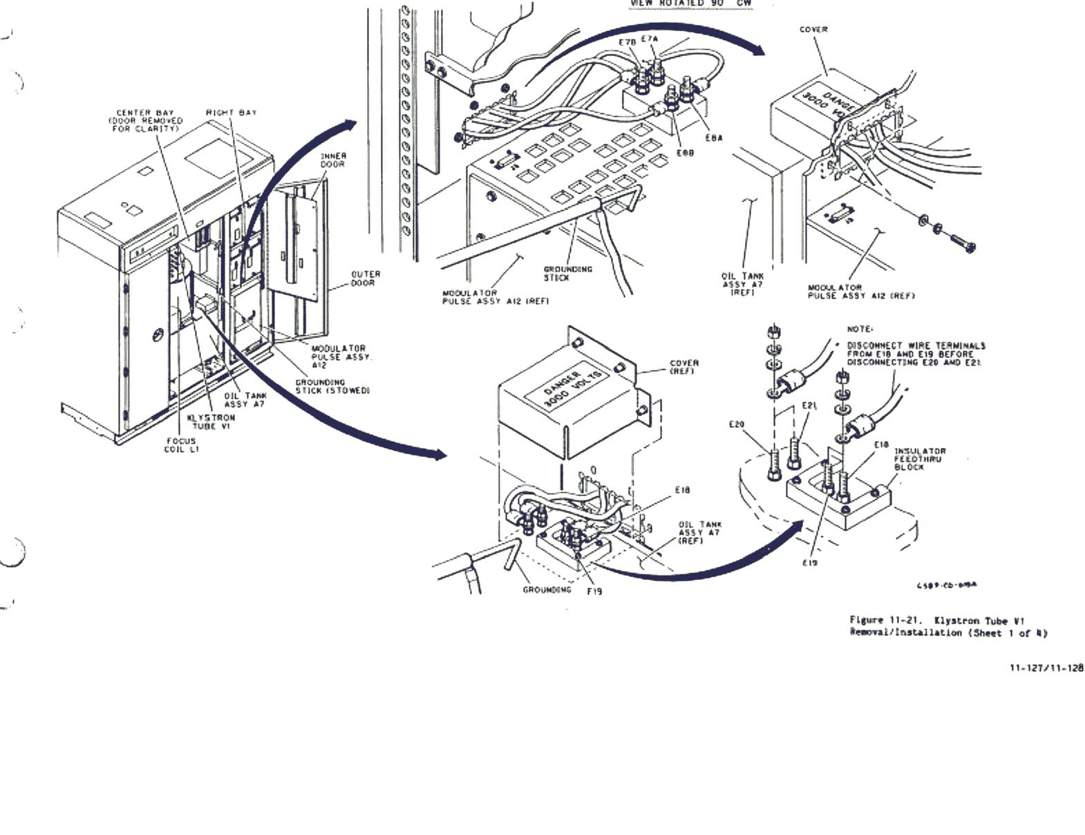
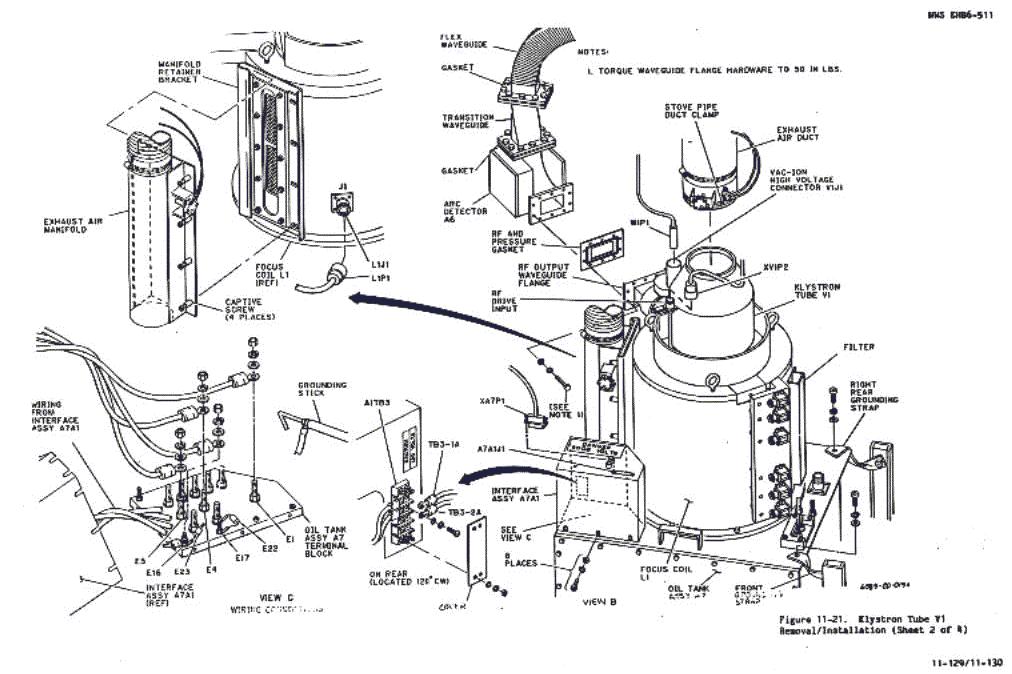
7.6.22.3 Removal Procedure.-
The following paragraphs describe how to remove klystron tube V1 and focus
coil L1. See figure 11-21, sheet 1 and proceed
as follows.
7.6.22.3.1 Removing Cables
and Waveguide.- Proceed as follows:

1. On top of modulator pulse
assembly A12, ground out terminals E7A, E7B, E8A,
and E8B with grounding stick provided.
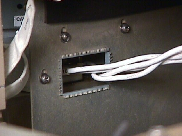
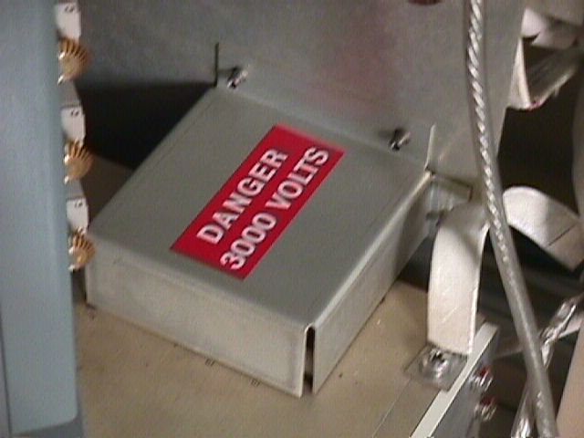
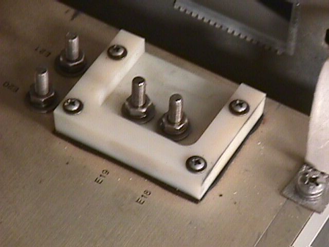
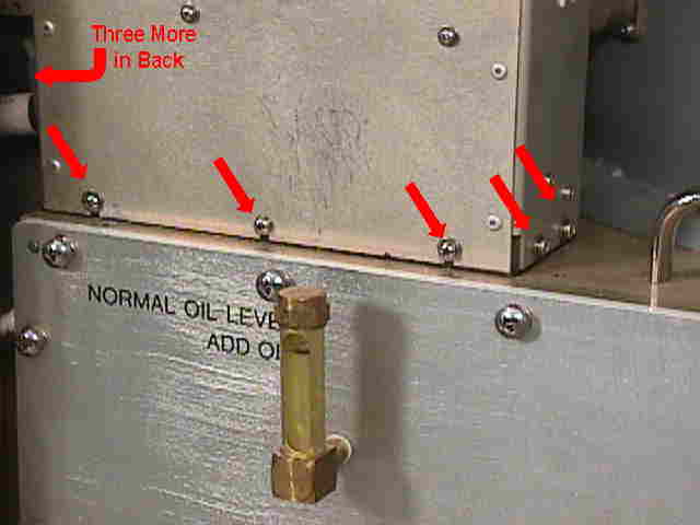
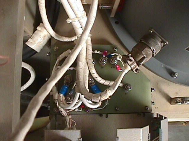
2. From cabinet right bay,
remove screws and associated hardware securing cover over oil tank
leads A7E18 through A7E21, and lift cover
away. See figure 11-21, sheet 1, view A,
and figure 11-22. Perform modulator pulse assembly
A12 access procedure paragraph 7.7.2.3
to gain access to the hardware securing the cover to leads A7E18 through
A7E21.
3. Use grounding stick to ground
terminals A7E18, A7E19, A7E20, and A7E21 on oil tank.
4. Disconnect
leads from terminals A7E18, A7E19, A7E20, and
A7E21 on oil tank.
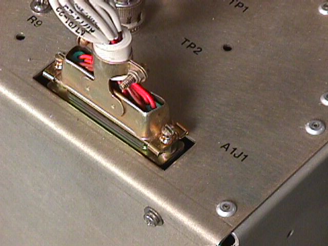
5. Disconnect connector A7Pl
from
oil tank interface assembly jack AlA1J1. See figure 11-21,
sheet 2, view B.
6. Loosen screws
securing oil tank interface assembly A7A1 to oil tank terminal block,
and lift assembly enough to expose terminals on oil
tank terminal block.
7. Ground all terminals on oil
tank terminal block, and disconnect leads from
terminals A7E1, A7E4, A7E5, and A7E16. See figure
11-21, sheet 2, view C.
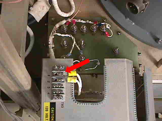
8. On exterior
of oil tank interface assembly A7A1, remove safety
cover on terminal board A1TB3.
9. Disconnect leads terminals
TB3-1A
and TB3-2A from terminal board A1TB3.
10. Disconnect connector L1P1
from focus coil connector L1J1.
11. Tie disconnected
terminal leads and cables clear of interface assembly A7A1 to gain access
to work area.
12. Place interface assembly
A7A1 in place on oil tank assembly terminal block. Do not replace hardware.
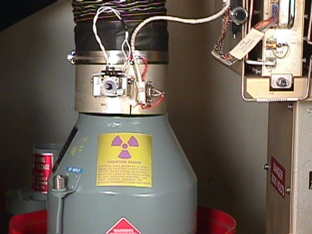
13. Disconnect exhaust
air manifold from focus coil by loosening four captive screws on right
side of manifold.
14. Disconnect exhaust air stove
pipe duct from klystron tube cooling shroud by loosening hose clamp
closest to klystron (lower of two hose clamps).
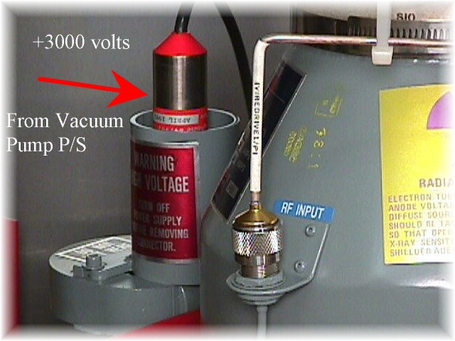
15. Disconnect connector W1P1
from ion pump high voltage connector V1J1 on klystron tube V1.
CAUTION
Waveguide pressure will discharge
when waveguide is loosened.
16. Remove
rigid coax W1O4 connected between rf attenuator AT1J2 and rf drive
input connector XV1P2 on klystron tube V1.
17. Disconnect rf output waveguide
flange on klystron tube V1 from arc detector
A6, and place dust cover on klystron waveguide opening.
18. Disconnect three grounding
straps on top of oil tank A7 (one strap on each rear corner and one on
right front corner).
19. Remove
tuner adjusting tools from focus coil L1.
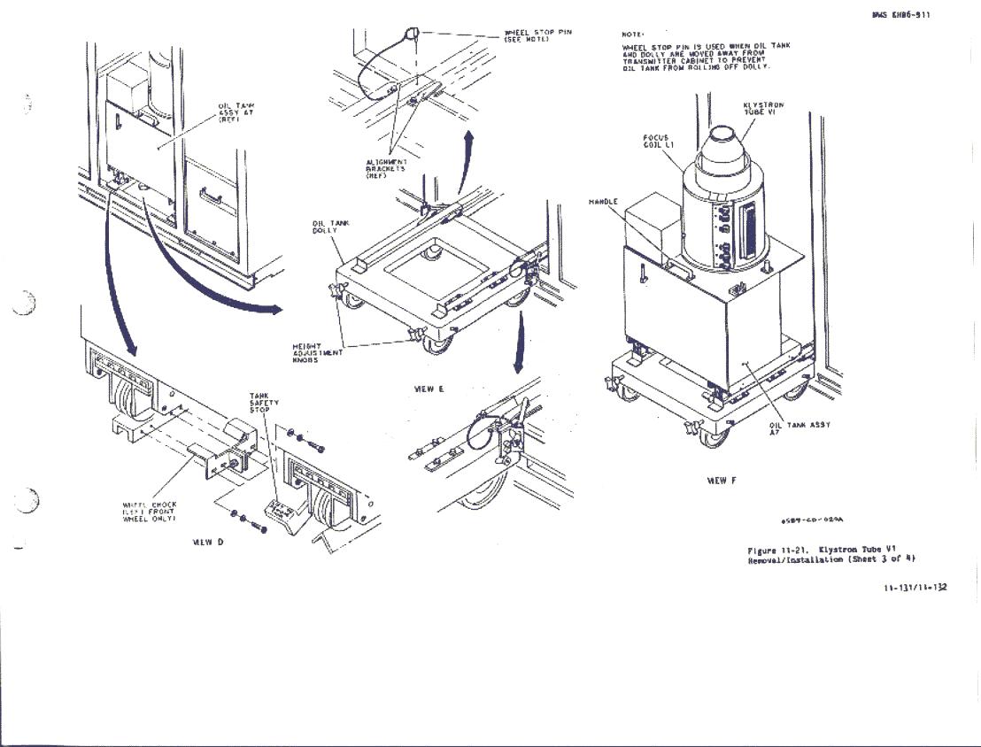
7.6.22.3.2
Transferring
Oil Tank to Oil Tank Dolly.- See figure 11-21,
sheet 3 and proceed as follows:
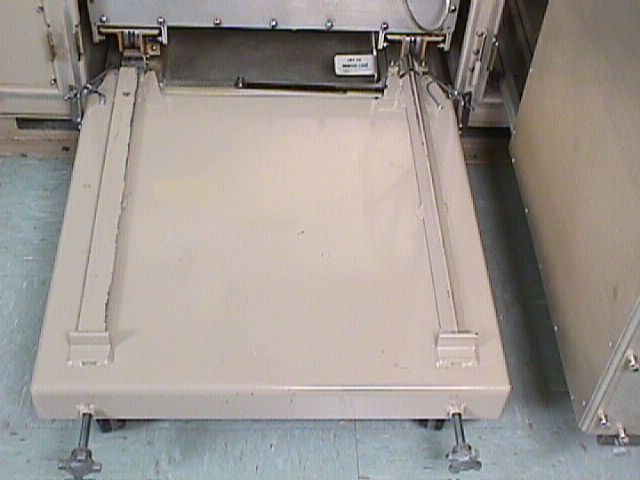
1. Set oil tank dolly
in place at threshold of transmitter cabinet center
bay. See figure 11-21, sheet 3, view E.
2. Adjust dolly height and horizontal
position, as necessary, to engage dolly alignment
tabs in cabinet rails.
3. Connect dolly cabinet hooks
to transmitter cabinet and tighten wing nuts.
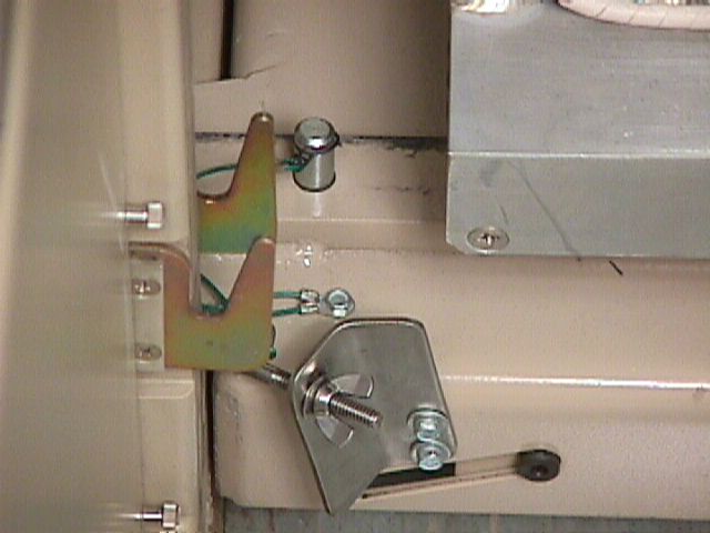
4. Remove
wheel chock from left front oil tank carriage wheel. See figure11-21,
sheet 3, view D.
CAUTION
The oil hoses and oil pump wires
are still connected to the rear of the oil tank. Take care not to damage
the oil hoses or wires during the removal of the oil tank assembly from
the cabinet.
It may be necessary to install
A12 Modulator assy. back into cabinet temporarily for ease of access
It also may be necessary to completely
remove the Focus Coil exhaust air Manifold for the A7 to be removed (As
seen in the Video)
5. Lift safety
stop and use oil tank handle to pull klystron tube and oil tank assembly
out of cabinet and onto dolly. See figure 11-21,
sheet 3, views D and F.
6. Insert dolly wheel
stop pin. See figure 11-21, sheet 3, view
E.
NOTE
If the front of the transmitter
cabinet is obstructed, the oil tank assembly may have to be rolled to a
clear area before disassembly can continue. Before releasing the dolly
from the cabinet, refer to paragraph
7.7.1.4.1 to drain the oil from the oil tank. Disconnect oil hoses
from heat exchanger and wires from A7TB1 and A7TB2 at the rear of the oil
tank.
7.6.22.3.3
Klystron
Tube V1 Removal Procedure.- Proceed as follows:
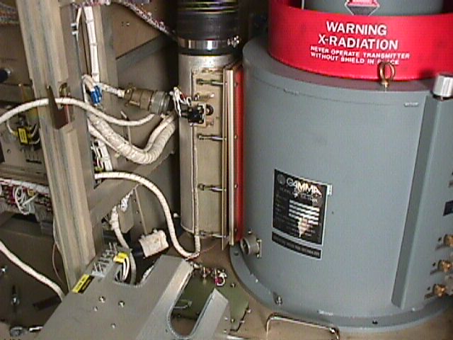
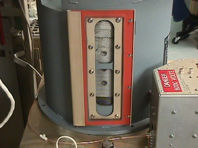
1. Remove hardware securing
x-ray shield to focus coil and remove x-ray shield from focus coil
L1. See figure 11-21, sheet 4, view G.
CAUTION
Never lift klystron tube V1
and focus coil L1 together. To prevent damage to klystron tuning gears,
make sure tuner adjustment tools have been removed from klystron before
lifting klystron.
2. Attach chain fall
to eyebolt provided in shelter overhead in front of transmitter cabinet.
See figure 11-21, sheet 4. Then attach plate
sling to chain fall hook.
WARNING
To prevent sling from separating
from klystron, make sure three nuts holding sling hooks are tight. (Recommended
torque is 25 foot-pounds.)
CAUTION
During tube extraction, proceed
slowly making sure sling hooks do not damage klystron shroud and klystron
is entirely supported by sling hooks and eyebolts.
The hook hardware should be
lubricated and checked for free play before use. Take care not to bump
or damage the waveguide components or vacuum pump connection.
3. See
figure 11-21, sheet 4, view H. Attach two lifting sling hooks to two
eyebolts on klystron tube V1.
4. Align chain fall directly
over klystron tube V1 by adjusting eyebolt in shelter overhead and oil
tank assembly A7.
5. One person should steady klystron
while a second person operates chain fall to carefully extract klystron
tube V1 from focus coil L1.
WARNING
Dielectric oil is a skin irritant.
Avoid prolonged skin contact. Breathing oil vapors for a prolonged time
is hazardous. Make sure the area is adequately ventilated. Oil on floor
is slippery and hazardous to maintenance personnel.
On ingestion of dielectric oil,
get medical attention. On eye contact, flush with water for at least 15-
minutes, and get medical attention. Frequent or prolonged skin contact
should be avoided. Inhalation of vapors or oil mist may irritate lungs.
Good industrial hygiene practice
requires the use of effective ventilation to remove any dielectric oil
vapors and mist. Skin contact is minimized by use of rubber gloves and
oil resistant, nonabsorbent clothing. After working with lubricants, wash
thoroughly with soap and water before eating or smoking. Change clothing
soaked with oil, and reuse only after laundering.
6. Once klystron tube V1 is
clear of focus coil L1, transfer oil tank assembly A7 from dolly to cabinet
(refer to paragraph 7.6.22.4.3). Place removed
klystron in klystron shipping container.
7. Place dust cover over klystron
waveguide opening.
8. Make sure 0-ring was extracted
with klystron. If 0-ring slipped off, recover it from oil tank.
9. Mop up oil that may have
dripped from klystron during transfer.
10. If it is not necessary to
remove focus coil L1, proceed to paragraph
7.6.22.4.2 for klystron installation procedures.
11. If tube will be out of oil
tank for extended period, cover oil tank opening to keep dust and other
foreign matter out of tank.
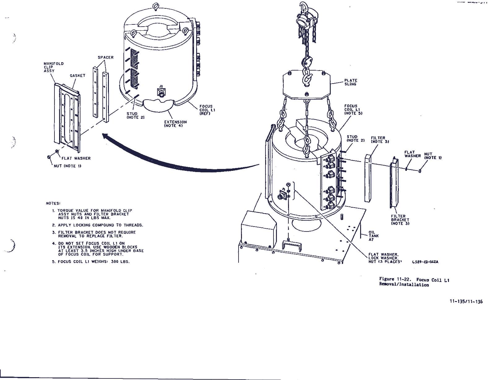
7.6.22.3.4
Focus
Coil L1 Removal Procedure.- After removing klystron tube V1, seefigure
11-22 and proceed as follows:
1. Remove filter and
filter bracket from air intake side of focus coil, (see figure
11-22).
Filter
Assy. Filter
Assy. Removed
2. Remove manifold clip assembly,
clip gasket, and two spacers from exhaust side of focus coil.
Manifold
Clip Assy. Manifold
Clip Assy. Removed
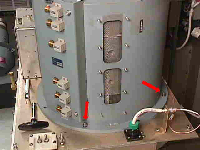
3. Remove mounting
flange hardware from focus coil base.
4. Attach lifting sling to chain
fall hoist lifting hook and three eyebolts on focus coil.
WARNING
To avoid personal injury and
equipment damage, use a lifting mechanism rated for at least 500 pounds.
Make sure shelter eyebolt will withstand the anticipated load.
CAUTION
Support the removed focus coil
with wooden blocks, when it is placed on a dolly to protect the tube that
extends below the coil mounting base.
5. Lift focus coil L1 clear of oil
tank and transfer oil tank from oil tank
dolly to cabinet (refer to
paragraph 7.6.22.4.3). Lower focus coil onto
dolly using wood blocks to protect
tube extension. Roll focus coil away
from transmitter cabinet.
CAUTION
Keep dust and other foreign
matter out of oil tank opening to prevent dielectric oil pollution.
7.6.22.4 Installation
Procedures.- The following paragraphs describe how to install focus
coil L1 and klystron tube V1. If only klystron tube V1 has been removed,
proceed to paragraph
7.6.22.4.2.
7.6.22.4.1
Focus
Coil L1 Installation Procedure.- See figure 11-22
and
proceed as follows:
WARNING
To avoid personal injury and
equipment damage use a lifting mechanism rated for at least 500 pounds.
Make sure shelter eyebolt will withstand the anticipated load.
1. Attach lifting sling to replacement
focus coil L1.
CAUTION
Take care not to damage the
stud bolts on top of oil tank.
2. With chain fall, lift focus
coil L1 and place in position. Transfer oil tank to oil tank dolly (refer
to paragraph 7.6.22.3.2). Place focus coil on
oil tank assembly A7 using attaching hardware, and remove sling.
3. Tighten focus coil holdout
bolts sufficiently to compress lock washers.
4. Attach air intake bracket
using locking/sealing compound on studs, flat washers, and nuts.
5. Torque air intake bracket
nuts to 40-inch-pounds maximum.
6. Install filter in bracket.
7. Attach manifold clip assembly,
clip gasket, and two spacers using locking/sealing compound on studs, flat
washers, and nuts. Torque nuts to 40-inch-pounds maximum.
7.6.22.4.2
Klystron
Tube V1 Installation Procedure.- Proceed as follows:

CAUTION
Avoid touching the ceramic portion
of the tube. All ceramic portions of the tube should be examined to make
sure they are clean and dry. Check that there are no foreign particles
of any kind between the flange and ceramic window.
NOTE
Examine klystron tube, and if
necessary, install 0-ring while the klystron tube is still in the transport
cart.
2. If necessary, transfer oil
tank from oil tank dolly to transmitter cabinet (refer to paragraph
7.6.22.4.3).
CAUT ION
Two people are required to remove
the klystron from the shipping container. One person should grasp the lower
end of the tube. The other person should grasp the upper portion of the
tube, exercising care not to lift on the rf output waveguide flange.
During klystron extraction,
proceed slowly making sure the sling hooks do not damage the klystron shroud,
and the klystron is entirely supported by sling hooks and eyebolts. Take
care not to bump or damage the waveguide components or vacuum pump connection.
4. Raise klystron tube
V1 above focus coil Li and transfer oil tank assembly A7 to oil tank dolly
(refer to paragraph 7.6.22.3.2). Line up tuning
ports on klystron tube V1 with holes in focus coil L1.
5. Lower klystron slowly guiding
it carefully in place in focus coil.
6. When klystron is seated in
focus coil, remove lifting sling.
WARNING
The klystron produces dangerous
X-radiation during operation. Never modify or alter klystron or other transmitter
components that might decrease radiation shielding. Never operate transmitter
unless all shielding is in place. X-ray exposure can occur without personnel
being aware, and serious personal injury or death may occur as a consequence
at some later date.
7. See figure
11-21, sheet 4, view G. Install x-ray shield on focus coil L1.
7.6.22.4.3
Transferring
Oil Tank from Dolly to Transmitter Cabinet.- Proceed as follows:
CAUTION
Ensure that all hoses, cables,
and wires are free and will not be damaged during placement of the oil
tank assembly into the cabinet.
1. See figure
11-21, sheet 3, view D. Remove wheel stop pin and push klystron tube
V1 and oil tank assembly A7 into transmitter cabinet until oil tank is
seated against rear wheel stop.
2. Install
wheel chocks on left front oil tank carriage wheel.
3. See figure
11-21, sheet 3, view E. Loosen wing nuts on dolly cabinet hooks, unhook
dolly from cabinet, and roll dolly away from transmitter cabinet.
7.6.22.4.4 Cable and Waveguide
Reconnection. - Proceed as follows:
CAUTION
Careful alignment between the
output flanges of the klystron and connecting waveguide components is essential
to prevent arcs. Errors in alignment can result in window failure and damage
to klystron tube V1.
1. Remove klystron waveguide
dust cover.
2. See figure
11-21, sheet 2, view B. Connect arc detector A6 to klystron tube waveguide
flange using a new rf gasket. Leave flange screws loose at this time so
that waveguide can be purged.
3. Set RDA power distribution
panel no. 2 circuit breaker CB8 to ON.
4. Set waveguide
pressurization unit UD6 ON/OFF switch to ON. Wait 10 minutes after
waveguide pressurization unit UD6 is turned on to allow waveguide to purge
properly.
NOTE
Waveguide flange hardware should
be torqued to 50 inch pounds maximum.. Torque waveguide flange screws to
50 inch pounds in sequence shown in figure 7-1.
Check for pressure integrity and correct any leaks before proceeding with
installation.
6. Connect three grounding
straps to top of oil tank. One strap is connected on right front; the remaining
two are connected to rear corners.
CAUTION
To avoid arcing and corona damage,
make sure that no other wires are within 1 inch of high voltage connection
A7E 1 when wires are installed and the interface box is replaced.
8. On exterior of oil tank interface
assembly A7A1, connect leads to terminal board terminals TB3-1A
and TB3-2A.
11. Connect
L1J1 to L1P1 on focus coil L1. Route this lead through interface assembly
box when setting box in place over oil tank terminal block.
NOTE
To avoid a cabinet door interlock
alarm when the transmitter is powered up, make sure that oil tank interface
assembly A7A1 is firmly seated.
16. Connect ion pump high voltage
connector
J1 on klystron tube V1 to plug W1P1.
17. Install
rigid coaxial W104 between RF drive input connector XV1P2 on klystron
tube and RF attenuator AT1J2.
19. Install cover over high
voltage terminals.
21. Replace klystron tuning
tools.
23. Close right bay inner door
and use key to lock right bay inner door.
24. Replace and close right
bay outer door.
25. Return interlock key to
HIGH VOLTAGE POWER circuit breaker CBl lock.
26. Replace and close center
bay door.
7.6.22.5 Related Alignment Procedures.
After replacing the klystron or focus coil: