Modulator Pulse Assembly Access
Procedure
7.7.2.2
Preliminary
Operations/Safety Precautions. Proceed as follows:
WARNING
Hazardous voltages are present
within the transmitter cabinet. Turn OFF transmitter high voltage power
by performing the procedures in paragraph 3.4.1.2
steps 1 through 5c. Take all standard precautions against electric shock.
Failure to comply may cause serious injury or death.
1. Turn OFF transmitter
high voltage power and place the transmitter in the maintenance mode by
performing the procedures in paragraph 3.4.1.2
steps 1 through 5c.
2. Open and remove right-bay
outer door.
3. Remove key from circuit breaker
CB1 lock.
WARNING
HIGH VOLTAGE
Filter Capacitor Bank A9 can
hold a lethal charge long after transmitter power has been removed. Discharge
Filter Capacitor Bank A9 after transmitter power is off and prior to transmitter
maintenance by opening the right-bay inner door while monitoring the charge
on VOLTAGE/CURRENT meter M4, at position 6, +280 Vdc power supply. Opening
the right-bay inner door releases the filter capacitor bank discharge plunger.
Failure to comply may cause serious injury or death.
4. Use key to unlock right-bay
inner door and open right-bay inner door.
5. Open and remove center-bay
door.
7.7.2.3
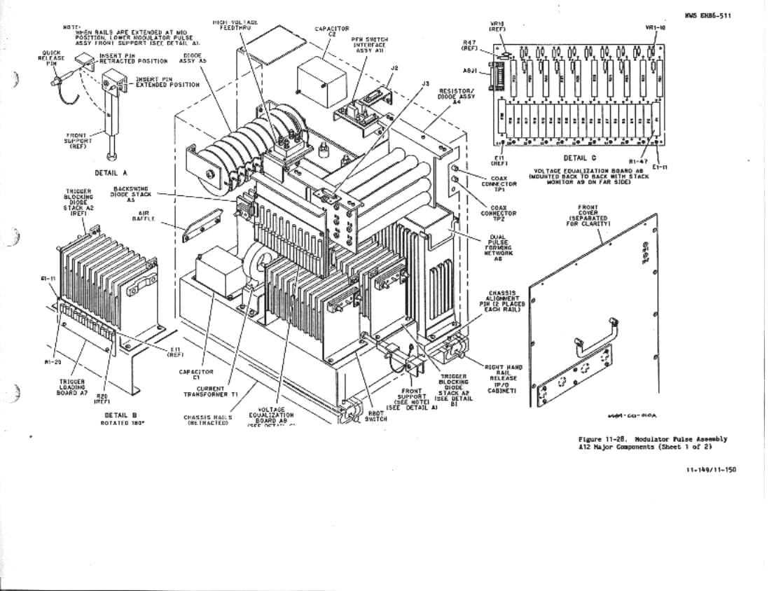
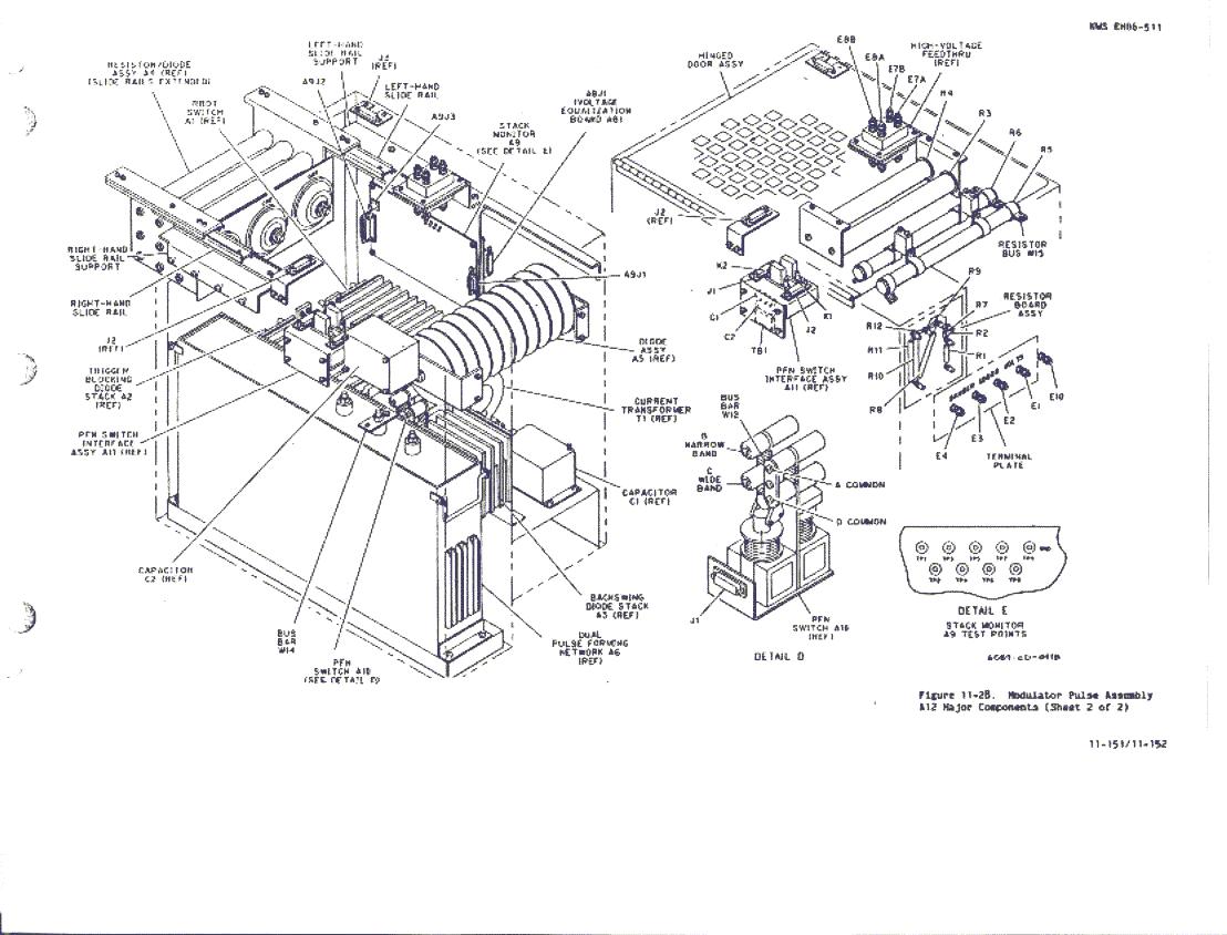
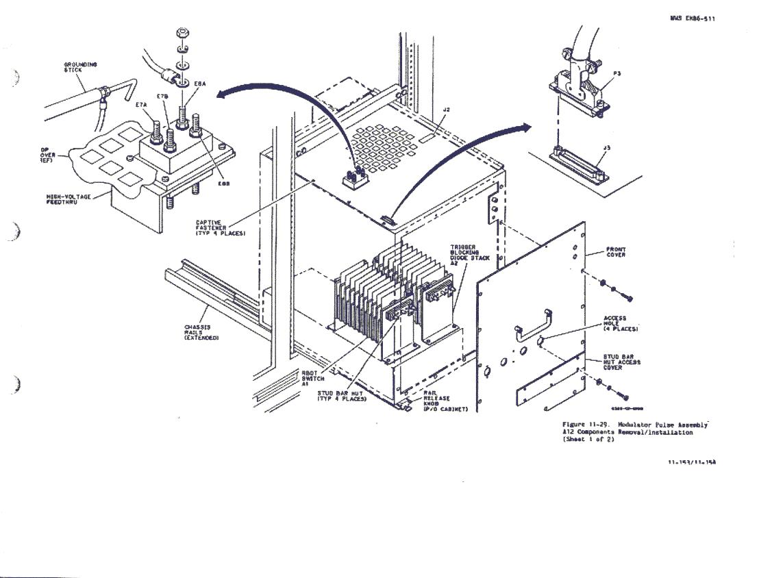
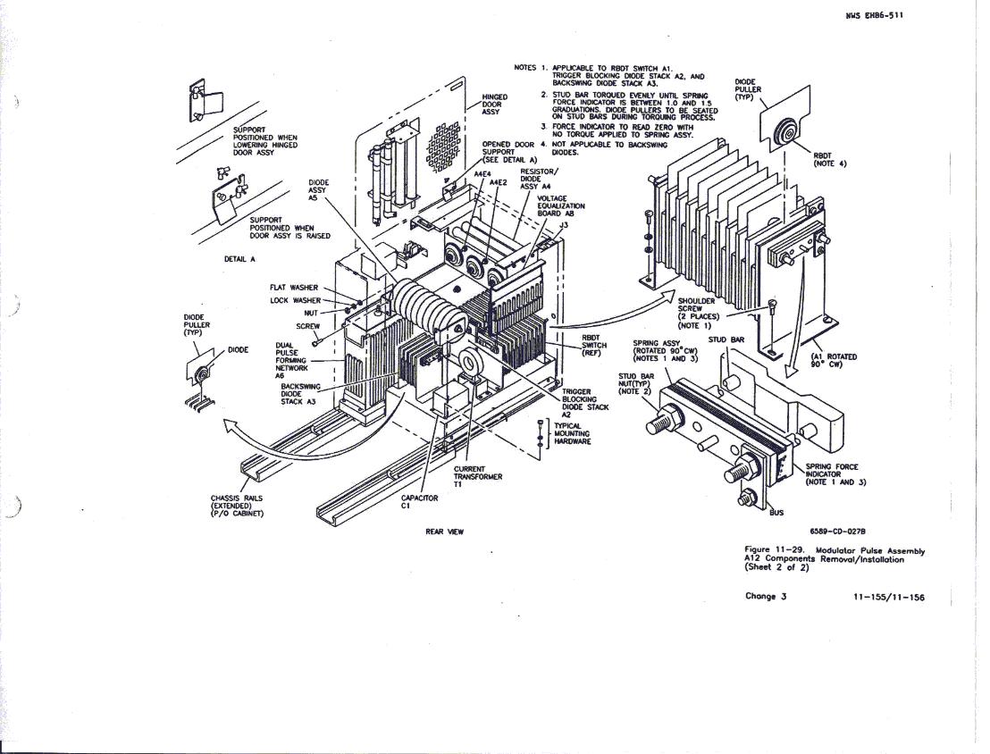
Modulator
Pulse Assembly UD3A12 Access Procedure. See figure 11-28, sheets
1 and 2, and figure
11-29, sheets 1
and
2 and proceed as follows:
2. Remove A10 in accordance
with paragraph 7.6.10.
3. Unscrew two captive screws
on front bottom of A12.
4.
Press both release knobs at bottom of A12 and slide A12 slowly out of cabinet
until braided ground wire connection is exposed on the top left side of
A12. Disconnect braided ground wire.
5. Disconnect J3 from P3 on
A12 top cover.
6. Slide A12 slowly out of cabinet
until stops are engaged and J2 is exposed. Disconnect J2 from P2.
7. Lower the front support at
bottom of A12 and lock into position using quick release. See figure
11-28, sheet 1, detail A.
8. Press both release knobs
at bottom of A12 and slowly pull A12 out of cabinet until access is gained
to terminals A12E7A, A12E7B, A12E8A, and A12E8B.
9. Use grounding stick located
in center-bay cabinet to ground out terminals A12E7A, A12E7B,A12E8A, and
A12E8B.
CAUTION
The high-voltage leads to terminals
A12E7A, A12E7B, A12E8A, and A12E8B will be strained or broken if care is
not exercised during Modulator Pulse Assembly A12 removal.
10. Remove high-voltage leads
from terminals A12E7A, A12E7B, A12E8A, and A12E8B and note locations to
ensure correct replacement.
11. Press both release knobs
at bottom of A12 and slowly pull A12 out of cabinet until stops are engaged.
12. Use grounding stick located
in center-bay cabinet to ground out terminals A12E1, A12E2, A12E3, A12E4,
and A12E10 on rear of A12. See figure 11-21, sheet
2.
13. Loosen captive fasteners
from A12 top cover.
14. Slowly tilt the top cover
up on its right edge and secure it in an upright position using the top
cover support. See figure 11-29, sheet 2,
detail A.