
3.4.1.2 Transmitter Power-down Procedure. To terminate the applications software program, perform steps 1 through 3. To obtain maintenance control, perform steps 1 through 4. To place the transmitter in the maintenance mode, perform steps 1 through 5b. To completely power-down the transmitter and remove all power to the transmitter cabinet, perform steps 1 through 5c.
1. Transfer transmitter control to local RDA terminal by performing the following steps at the UCP terminal:
a. Verify that RPG Main Menu is displayed. If not, press key Fl to display RPG Main Menu.
In the steps that follow, letters typed on a terminal are capitalized, and letters that appear on a terminal screen are enclosed in quotes.
b. On RPG Main Menu, select RDA Control Menu by typing RD <return> on command line.c. Check RDA control field in status area of main menu. If control field displays "RDA CNTL RPG" proceed to step 1d. If control field displays "RDA CNTL RDA or "RDA CNTL(BLANK)" proceed to step 2a.
d. Enable local control of RDA by typing EN <return> on command line of RDA Control Menu. Verify that feedback line displays "COMMAND EXECUTED RD EN".
NOTE
Reset the intrusion alarm upon entering the RDA shelter, if required.
2. With RDA terminal in application mode, perform following steps:
a. If RDA terminal is in system console mode, press SHIFT and PORT keys simultaneously. Observe that the cursor moves to the lower half of the screen (if in split-screen mode) or an application terminal menu appears (if in full-screen mode).
NOTE
For NWS Redundant systems, switch must be set to position A (LOCAL).
b. Verify that RDA Main Menu is displayed. If not, type MAIN <return> on command line of current menu to obtain RDA Main Menu.c. At main menu of RDA application program, request local control from UCP by typing RELC <return> on command line. Observe that "RELC - ACCEPTED" is displayed on feedback line of menu. "LOC" appears in the 'MODE" fields to indicate that RDADP is now in local control.
CAUTION
Do not use the SHIFT and CLEAR keys while running the RDA application program. Pressing SHIFT and CLEAR keys will cause the keyboard to lock-up.
3. To terminate RDA program and place RDA in standby mode, perform following steps at RDA terminal:
a. On RDA Main Menu, type STRY <return> on command line. Observe that "STBY ACCEPTED" is displayed on feedback line of menu.4. At transmitter, obtain maintenance control with high voltage off by performing following steps. See figure 3-5 for the locations of controls and indicators.b. In status area of RDA Main Menu, observe that the antenna is moved to the park position at approximately 23 degrees elevation and 0 degrees azimuth. Observe that "AZ 0 DEG" (approximately) and "EL 23 DEG" (approximately) are displayed. (In redundant systems, status area is blank if working on the non-controlling channel).
c. On RDA Main Menu, type TERP <tab> on command line. Observe that TERP" is displayed on the command line and the cursor moves to the parameter line.
d. Type <password> <return> on parameter line. Observe that 'TERP ACCEPTED is displayed.
e. Simultaneously press SHIFT and PORT keys, then wait for application tasks to terminate. (Approximately 30 seconds)
a. On transmitter control panel Al, at operation and test sections, verify that transmitter is in system control by observing CONTROL MAINT/SYSTEM switch/indicator. Verify that SYSTEM indicator is lit (amber) anMAINT indicator is not lit.
NOTE
Steps b and c verify that high voltage is off.
b. Observe CONTROL HV ON/NO CONTROL switch/indicator. Observe that HV ON indicator is not lit, and NO CONTROL indicator is lit (amber).c. Observe CONTROL HV OFF/NO CONTROL switch/indicator. Observe that HV OFF indicator is lit (white), and NO CONTROL indicator is lit (amber).
d. Place transmitter under maintenance control by pressing and releasing CONTROL MAINT/SYSTEM switch/indicator. Observe that MAINT indicator is lit (white) and SYSTEM indicator is not lit.
e. On CONTROL HV OFF/NO CONTROL and CONTROL HV ON/NO CONTROL switch/indicators, verify that NO CONTROL indicators are not lit.
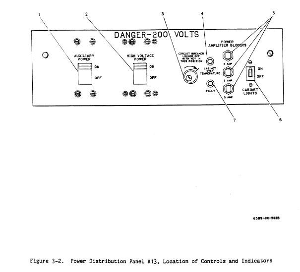
5. Turn off power to transmitter by performing following steps. See figure 3-2 for locations of controls and indicators.
a. At transmitter power distribution panel UD3A13, set the CABINET LIGHTS (CB3) and HIGH VOLTAGE POWER (CB1) circuit breakers to OFF. Then set the AUXILIARY POWER (CB2) circuit breaker to OFF.b. Lock HIGH VOLTAGE POWER ON/OFF circuit breaker CB1 to OFF position by rotating interlock key clockwise to lock position.
c. In single channel systems, at power distribution panel no. 2, turn OFF circuit breakers CB1, CB3, CB5 (ganged), and CB7. In redundant systems, at Secondary Panel #1 for channel 1 or Secondary Panel #2 for channel 2, turn OFF circuit breakers CB1, CB3, CB5 (ganged), and CB7.
NOTE
In Redundant systems, Secondary Panel #1 controls Channel 1, and Secondary Panel #2 controls Channel #2.