7.7.2.15
Modulator Pulse Assembly
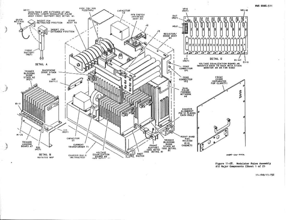
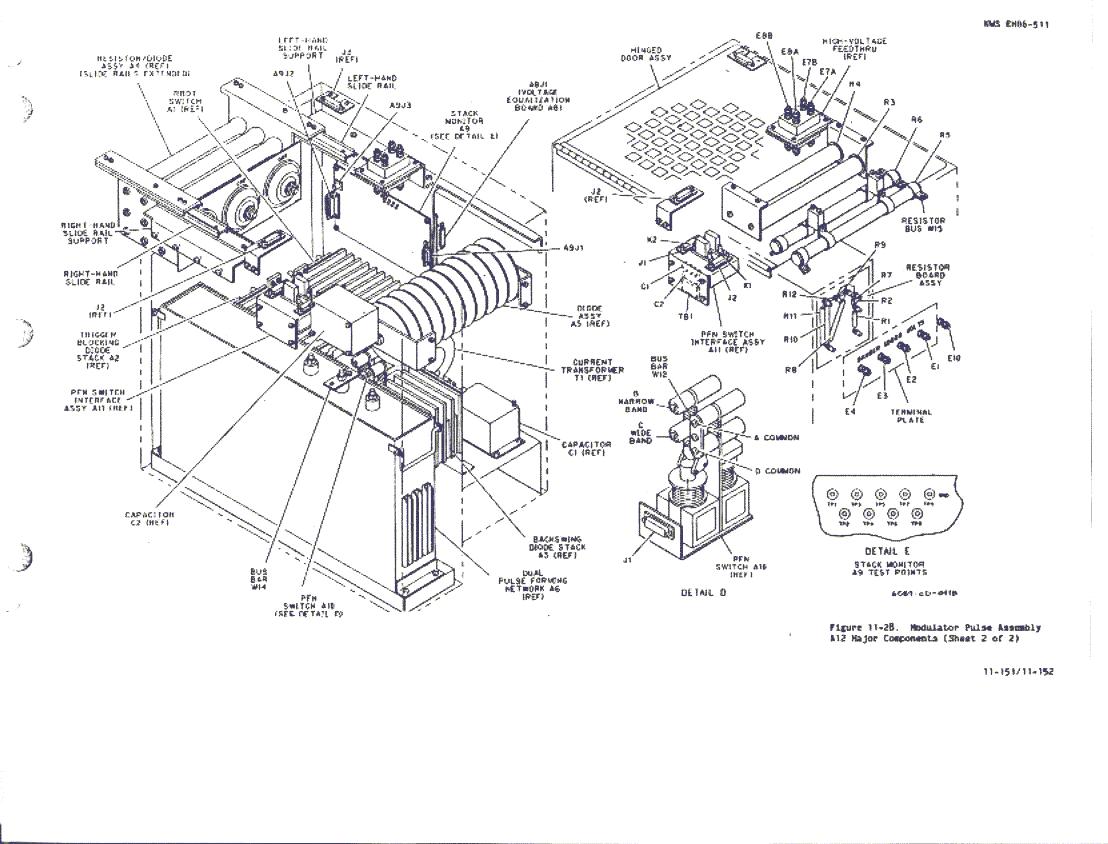
UD3A12 Closure Procedure. See figure 11-28, sheets 1
and 2, and proceed as follows:
1. Ensure that steps in paragraph 7.7.2.2 have been accomplished.2. Make cursory check for damaged wires, disconnected leads, and tools left inside A12.
3. Disengage and secure top cover support and close A12 top cover.
4. Tighten captive fasteners on A12 top cover.
5. Press both release knobs at bottom of A12 and while holding the disconnected cables clear, slowly slide A12 into cabinet until stops are engaged.WARNING The high-voltage leads to terminals A12E7A, A12E7B, A12E8A, and Al2E8B will be strained or broken if care is not exercised during Modulator Pulse Assembly A12 closure.
6. Raise and secure the front support at the bottom of the A12.
7. Reconnect J2 to P2 on A12 top cover.
8. Press both release knobs at bottom of A12 and slowly slide A12 into cabinet until braided ground wire can be reconnected.
9. Reconnect J3 to P3 on A12 top cover.
10. Slide A12 into cabinet and tighten two captive screws on the bottom of A12.CAUTION When moving the Modulator Pulse Assembly A12, make sure the rear exhaust duct in the cabinet does not pinch the wiring connected to the rear interface plate.
11. Reconnect high-voltage leads to terminals A12E7A, A12E7B, A12E8A, and A12E8B at same locations as noted in paragraph 7.7.2.3 step 4.
12. Replace A10 in accordance with paragraph 7.6.10.4.
13. Close right-bay inner door and use key to lock right-bay inner door.
14. Return interlock key to HIGH VOLTAGE POWER circuit breaker CB1 lock.
15. Replace and close center-bay door.
16. Replace and close right-bay outer door.
17. Return the transmitter to remote control by performing the procedures in paragraph 3.4.1.5 steps 1 through 4.