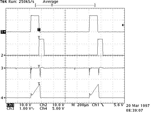
Ch 1 = TP1 Ch 2 = TP2 Ch 3 = TP6 Ch 4 = TP7 Note: Channel 3 is AC coupled because it rides on 3.5 VDC RDASOT, Short/5 , klystron output source, scope set to average of 10
Return to Charge System - Failure