BACKGROUND
SIGNAL SOURCE
The VACUUM PUMP CURRENT METER signal (see figure 11-3
sheet 6) provides a sample of the vacuum pump current for fault monitoring.
SIGNAL DESTINATION
The VACUUM PUMP CURRENT METER signal goes to Control Card
Rack (see 11-7 sheet 15) via J30 pin 21. There its name is changed
to VPPSI as it leaves at bubble 1511-2. This signal goes to the Metering
Interface A1A2 (see figure 11-7 sheet 2) at bubble 1511 where it name become
VPPSISAMPIN. VPPSISAMPIN appears to be used by the E/I meter but
it is not, but its using the same wiring harness which services the Metering
Interface board A1A2. The signal leaves the Metering Interface board
as VPPSISAMPOUT at bubble 214-3 for the Transmitter Control Panel's Vacuum
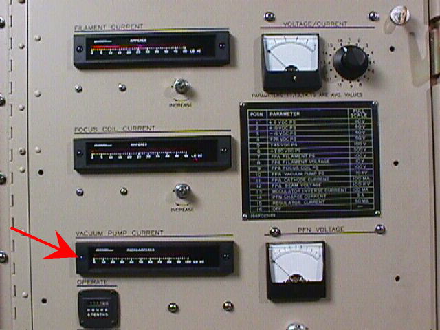
Pump Current Meter A1M3(see figure 11-7 sheet 3). The Vacuum
Pump Current Meter is a microampere meter which display the amount
of current that is used in normal operation of the transmitter. Normally,
A1M3 will display very little current being drawn by the Vacuum Pump.
As a result only the high limit is set on the Meter. When the high
limit is reached, pin 2 on the back of the meter which is normally High
will goes Low. This signal leaves A1M3 as VPPSIHI- at bubble 314-10
for the Transmitter RMS Interface board A3A3 (see 11-7 sheet 10). At bubble
314 VPPSIHI- is changed to KLYVPPSI- and is reported on the Fault Bus during
Port05EN- as Transmitter Data (TDATA), it also exit at bubble 1004-11
to remove Transmitter Available at 1004 (see figure 11-7 sheet 11).
As KLYVACI- at bubble 1017-1 goes the the A1A1 Fault Display Panel as KYLVACCUR--
to turn on the Klystron Vacuum Pump Current lamp at 1017 (see 11-7 sheet
1).
LIMITS AND FAULTS
The Klystron Vacuum Pump Current Fault light on the A1A1
Fault Display Panel will come on when the high limit on the A1M3 meter
is reached. The High limit on the back
of the meter is set for 20 microamps.